AVIONICS AND ASTRIONICS
TABLE OF CONTENTS
1. Avionics…………………………………………………………………………….3
2. History……………………………………………………………………………...3
3. Non-directional radiobeacon……………………………………………………….4
4. VHF Omni Range…………………………………………………………………..4
5. Instrument Landing System………………………………………………………...4
6. Transponder………………………………………………………………………...5
7. DME………………………………………………………………………………...5
8. LORAN……………………………………………………………………………..6
9. Auxiliary and diagnostic systems…………………………………………………..6
10. Recent Advances…………………………………………………………………....6
11. GPS…………………………………………………………………………………6
12. Glass cockpits……………………………………………………………………....8
13. Flight Data Recorder………………………………………………………………..9
14. History……………………………………………………………………………...9
15. Design……………………………………………………………………………..10
16. EPIRB……………………………………………………………………………..11
17. Statutory emergency equipment…………………………………………………..13
18. Types……………………………………………………………………………....13
19. Current types………………………………………………………………………13
20. Obsolete types……………………………………………………………………..14
21. Registration………………………………………………………………………..15
22. How they work…………………………………………………………………….15
23. GPS-based…………………………………………………………………………16
24. High-precision…………………………………………………………………….17
25. Traditional ELT…………………………………………………………………...17
26. Location by Doppler………………………………………………………………18
27. Satellites…………………………………………………………………………...19
28. History…………………………………………………………………………….19
REFERENCES…..………………………………….…………………………………....21
1. AVIONICS
The onboard electronics used for piloting an aircraft are called avionics (AVI-ation electr-ONICS). Avionics include communications and navigation systems, autopilots, and electronic flight management systems (FMS). Onboard electronics that are unrelated to piloting tasks, such as video systems for passengers, are sometimes considered avionics as well. Many of these devices include embedded computers.
2. HISTORY
Radiotelephone (two way voice radio) systems have been installed in aircraft since before World War II, and have been widely used for mission coordination and air traffic control. Early systems used vacuum tubes, and because of their weight and size, were installed out of the way with only a control head in place in the flight deck. Standardization on VHF frequences occurred shortly after World War II, and transistor radio systems replaced the tube-based systems shortly afterward. Only minor changes have been made to these systems since the 1960s.
The earliest navigation systems required the pilot or navigator to wear headphones and listen to the relative volume of tones in each ear to determine which way to steer on course.
Later, navigation systems developed along six separate paths:
- NDB/ADF systems
- VOR systems
- ILS systems
- ATCRBS Transponders
- Distance Measuring Equipment
- GPS receivers
3. NON-DIRECTIONAL RADIOBEACON
The NDB (non-directional radiobeacon) was the first electronic navigation system in widespread use. The original radio range stations were high-power NDBs, and followed nighttime routes previously delineated by colored light beacons. DF (direction finder) and ADF (Automatic Direction Finder) avionics can receive signals from these. A needle shows the pilot the relative heading toward the station compared to the centerline of the aircraft. NDBs use the LF and MF bands, and are still in use today (2005) at smaller airports because of their low cost but their use is quickly being supplanted by GPS. This is due mostly from the higher cost of ADF equipment in the aircraft and maintaining the NDB stations.
4. VHF OMNI RANGE
The VOR system (VHF omni range) is less prone to interference from thunderstorms, and provides improved accuracy. It is still the backbone of the air navigational system today. VOR receivers allow the pilot to specify a radial, that is, a line extending outward from the VOR transmitter at a particular angle from magnetic north. Then, a course deviation indicator (CDI) shows the amount by which the aircraft is off the chosen course. Distance measuring equipment (DME) was added to many VOR transmitters and receivers, allowing the distance between the station and the aircraft to be shown .
5. INSTRUMENT LANDING SYSTEM
The instrument landing system (ILS) is a set of components used to navigate to the landing end of a runway. It consists of lateral guidance from a localizer, vertical guidance from a glideslope, and distance guidance from a series of marker beacons. Optional components include DME and a compass locator, the name given to an NDB placed at the start of the final approach course.
6. TRANSPONDER
The transponder is a transceiver that receives "interrogations" from air traffic control radar systems and replies with a digital code. This secondary radar reply permits the radar system to detect the aircraft more reliably and at greater distances than are possible with primary radar. This system of secondary radars and transponders is known collectively as the air traffic control radar beacon system, or ATCRBS.
A basic "mode A" transponder responds with a 4-digit code with each digit ranging from 0 to 7. This is called a 4,096 code transponder. This pilot sets the code according to the type and status of the flight or as directed by air traffic control.
A "mode C" transponder also replies with the pressure altitude of the aircraft encoded to the nearest 100 feet (30 m). Modern "mode S" transponders can respond with a longer digital identifier that is unique for each aircraft (thus allowing each aircraft to be uniquely identified even when there is no voice communication between the aircraft and air traffic control) and can receive digital traffic information from air traffic control radar systems and display them for the pilot.
An IFF transponder, "Identification friend or foe", is used in military aircraft and has additional modes of operation beyond those used in civil air traffic control.
7. DME
Distance Measurement Equipment (DME) is used to give the pilot the information of its distance away from the VOR station, thus with a bearing and distance from a particular known VOR station a pilot can fix his exact position. Such systems are referred to as VOR/DME. DME is also part of a military navigation system widely used in the US, the TACAN (TACtical Air Navigation). A ground station combining VOR and TACAN is known as VOR-TAC. Needless to mention, the frequencies for the VOR and DME or VOR and TACAN are paired by international standards, thus once a pilot tunes onto a particular VOR frequency the airborne equipment will automatically tunes on the co-located DME or Tacan.
8. LORAN
For a time, LORAN systems, which provide navigational guidance over large areas, were popular particularly for general aviation use. They have declined in popularity with the commercial availability of GPS service.
9. AUXILIARY AND DIAGNOSTIC SYSTEMS
Commercial aircraft are expensive, and only make money when they are flying. For this reason, efficient operators perform as much service as possible in-flight, and during the turn-around time in a terminal. To make this process possible, embedded computer systems test aircraft systems, and also collect information about faults in equipment that they control. This information is normally collected in an on-board maintenance computer, and sometimes transmitted ahead to help order spares. Although this sounds ideal, in real life, these self-test systems are often not considered flight-critical, and therefore they are sometimes unreliable, and trusted only to indicate that a device requires service.
10. RECENT ADVANCES
Avionics have changed significantly with the advent of the GPS receiver and "glass cockpit" display systems.
11. GLOBAL POSITIONING SYSTEM (GPS)
The use of the Global Positioning System (GPS) has changed aircraft navigation both in the en-route phase and approach (landing) phases of flight.
Aircraft have traditionally flown from one radio navigation aid ("navaids") to the next (e.g., from VOR to VOR). The paths between navaids are called airways. While this is rarely the shortest route between any two airports, the use of airways was necessary because it was the only way for aircraft to navigate with precision in instrument conditions. The use of GPS has changed this, by allowing "direct" routing, allowing aircraft to navigate from point to point without the need for ground-based navigation. This has the potential to save significant amounts of both time and fuel while en-route.
However, "direct-to" routing causes non-trivial difficulties for the air traffic control (ATC) system. ATC's basic purpose is to maintaining appropriate vertical and horizontal separation between aircraft. The use of direct routing makes maintaining separation harder. A good analogy would be vehicular traffic: Roads are comparable to airways. If there were no roads and drivers simply went directly to their destination, significant chaos would ensue (e.g., large parking lots without barriers or lines). ATC does give clearance for direct routing on occasion, but its use is limited. Projects like free flight propose to computerize ATC and allow greater use of direct routing by identifing potential conflicts and suggesting maneuvers to maintain separation. This is much like the existing Traffic Collision Avoidance System, but on a larger scale and would look further forward in time.
GPS has also significantly changed the approach phase of flight. When horizontal visibility and vertical cloud ceilings are below visual flight rules (VFR) minimums, aircraft must operate under instrument flight rules (IFR). Under IFR, aircraft must use navigational equipment for horizontal and vertical guidance. This is particularly important in the approach and landing phases of flight. The path and procedure used to land on a particular runway is called an instrument approach.
IFR approaches traditionally required the use of ground-based navaids such as VOR, NDB and ILS. GPS offers some significant advantages over traditional systems in that no ground-based equipment is required, reducing cost. This has allowed many smaller airports that cannot justify ILS equipment to now have instrument approaches. GPS receivers for aircraft are also less expensive, use a single small antenna, and require virtually no calibration.
The downside to GPS approaches is that they have higher minimum visibility and ceiling requirements. ILS typically require a cloud ceiling no lower than 200 feet above ground level and horizontal visibility greater than 1/4 mile, while GPS minimums are typically never less than 400 feet and 1 mile. This difference in minimums is because GPS approaches offer horizontal guidance only. Vertical guidance is possible, but GPS accuracy in the vertical is not as high as in the horizontal. To solve this problem, the FAA has implemented the Wide Area Augmentation System (WAAS). GPS receivers with WAAS capability have typical vertical accuracy of 2-3 meters. This is sufficient for ILS-type approaches, i.e., those with vertical navigation. GPS/WAAS receivers certified for vertical navigation GPS approaches are slowly coming to the market.
Although the FAA was initially slow to allow the use of GPS in IFR approaches, the number of published GPS approaches is climbing significantly. However, because ILS has lower minimum visibility and ceiling requirements, ILS remains the "best" type of approach, and the FAA has committed to maintaining ILS installations.
12. GLASS COCKPITS
Advances in computing power and flat panel LCD displays have made the glass cockpit possible. Glass cockpits are loosely defined as aircraft flight decks where information is presented on one or more electronic displays. They offer significantly lower pilot workloads and improved situational awareness over traditional "steam gauge" flight decks.
Glass cockpits were first introduced on airliners and military aircraft. Recently, they have started to appear in general aviation aircraft such as the Cirrus Design SR20 and Lancair designs.
13. FLIGHT DATA RECORDER
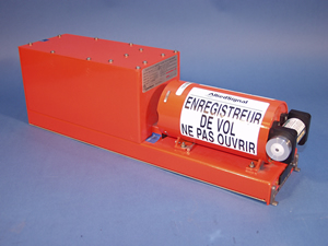
An example of a Flight Data Recorder
The flight data recorder (FDR) refers generically to a class of recorders used to record specific aircraft performance parameters. A separate device is the cockpit voice recorder (CVR), although some recent types combine both in one unit. Popularly known as the black box used for aircraft mishap analysis, the FDR is also used to study air safety issues, material degradation, and jet engine performance. These ICAO regulated "black box" devices are often used as an aid in investigating aircraft mishap, and these devices are typically one of the highest priorities for recovery after a crash, second only to bodies of victims. The device's shroud is usually painted bright orange and is generally located in the tail section of the aircraft.
14. HISTORY
The first prototype FDR was produced in 1957 by Dr David Warren of the then Aeronautical Research Laboratories of Australia. In 1953 and 1954, a series of fatal mishaps on the de Havilland DH106 Comet prompted the grounding of the entire fleet pending an investigation. Dr Warren, a chemist specializing in aircraft fuels, was involved in a professional committee discussing the possible causes. Since there had been no witnesses, and no survivors, Dr Warren began to conceive of a crash survivable method to record the flight crew's conversation, reasoning they would likely know the cause.
Despite his 1954 report entitled "A Device for Assisting Investigation into Aircraft Accidents" and a 1957 prototype FDR named "The ARL Flight Memory Unit", aviation authorities from around the world were largely uninterested. This changed in 1958 when Sir Robert Hardingham, the Secretary of the UK Air Registration Board, became interested. Dr Warren was asked to create a pre-production model which culminated into the "Red Egg", the world's first commercial FDR by the British firm, S. Davall & Son. The "Red Egg" got its name from the shape and bright red color. Incidentally, the term "Black Box" came from a meeting about the "Red Egg", when afterwards a journalist told Dr Warren, "This is a wonderful black box."
15. DESIGN
The design of today's FDR is largely governed by the European Organisation for Civil Aviation Equipment in its EUROCAE ED-122 (Minimum Operational Performance Specification for Crash Protected Airborne Recorder Systems). In the United States, the Federal Aviation Administration (FAA) regulates all aspects of U.S. aviation, and cites design requirements in their Technical Standard Order, TSO-C124a, which mostly refers back to ED-122 (like many other countries' aviation authorities).
Currently, EUROCAE specifies that a recorder must be able to withstand an acceleration of 3400 g (33 km/s²) acceleration for 6.5 milliseconds. This is roughly equivalent to an impact velocity of 270 knots and a deceleration or crushing distance of 450 mm. Additionally, there are requirements for penetration resistance, static crush, high and low temperature fires, deep sea pressure, sea water immersion, and fluid immersion.
Modern day FDRs are typically plugged into the aircraft's fly-by-wire main data bus. They record significant flight parameters, including the control and actuator positions, engine information and time of day. There are 88 parameters required as a minimum by current U.S. federal regulations (only 29 were required until 2002), but some systems monitor many more variables. Generally each parameter is recorded a few times per second, though some units store "bursts" of data at a much faster frequency if the data begins to change quickly. Most FDRs record more than a day's worth of data.
Recently aviation authorities have begun to place FDRs in the empennage. In this position, the entire front of the aircraft acts as a "crush zone" to reduce the shock that reaches the recorder. Also, modern FDRs are typically double wrapped, in strong corrosion-resistant stainless steel or titanium, with high-temperature insulation inside. Additionally, since the recorders are sometimes crushed into unreadable pieces, or never located, some modern units are self-ejecting, with radio and sonar beacons (i.e. emergency locator transmitter).
16. EMERGENCY POSITION-INDICATING RESCUE BEACON
Emergency position-indicating rescue beacons (EPIRB), Emergency Locator Transmitters (ELT) and Personal Locator Beacons, are radio transmitters that operate as part of the Cospas-Sarsat Satellite System. When activated, the beacons send out a distress signal that allows the beacon to be located by the satellite system and search and rescue aircraft to locate the people, boats and aircraft needing rescue. They are a component of the Global Maritime Distress Safety System.
EPIRBs are used for maritime emergencies, where ELTs are used in aircraft applications and PLBs are used for personal use.
The basic purpose of the emergency beacons is to get people rescued within the "golden day" when the majority of survivors can still be saved.
Between 1982 and 2002, these systems enabled the rescue of 14,700 people. As of 2002, there are roughly 82,000 registered beacons, and over 500,000 of the older unregistered type.
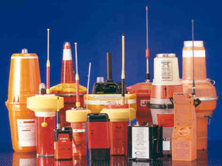
Most beacons are brightly-colored, waterproof, fit in a cube about 30 cm on a side, and weigh 2-5 kg. They can be purchased from marine suppliers, aircraft refitters, and (in Australia and the United States) hiking supply stores. The units have a useful life of 10 years, operate across a range of conditions (-40°C to 40°C), and transmit for 24 to 48 hours. As of 2003 the cost varies from US$139 to US$3000, with varying performances. Although modern systems are significantly superior to older ones, even the oldest systems provide an immense improvement in safety, compared to not having a beacon.
17. STATUTORY EMERGENCY EQUIPMENT
Most general aviation aircraft in the U.S. are required to carry an ELT, depending upon the type or location of operation, while most commercial airliners are not. 14 CFR 91.207. However, in commercial aircraft, a cockpit voice recorder or flight data recorder must contain an underwater detection beacon.
Most commercial off-shore working vessels with passengers are required to carry a self-deploying EPIRB, while most in-shore and fresh-water craft are not.
18. TYPES
There are two types: manually activated, and automatically activated.
In the U.S., offshore beacons are investigated and victims rescued by the Coast Guard. On-shore beacons are investigated by local search and rescue services in Alaska. The Air Force Rescue Coordination Center is charged with land-based emergency signals, usually dispatching volunteer members from The United States Air Force Auxiliary Civil Air Patrol. In the U.S. there are no published notification systems for other locations.
In the U.S. no special license is required, but serial-number registration is required. In some jurisdictions, larger boats and ships are required to carry an ELT.
19. CURRENT TYPES
Current EPIRBs are generally divided into three classes; Category I, Category II, and Class B (or Category B).
- Category I EPIRBs are considered the best but are also the most costly. Category I EPIRBs can be either activated manually or set to activate automatically in the event of a disaster at sea. These EPIRBs are generally housed in a specially designed bracket on deck and the buoyant beacon is designed to rise to the surface and emit two signals, an emergency homing signal on 121.5 MHz and a digital identification code on 406 MHz that can be used to identify the stricken vessel. Category I EPIRBs used in American waters must be registered with NOAA.
- Category II EPIRBs are similar to Category I EPIRBs but are generally manual activation only. Also like Category I EPIRBs, Category II units must be registered. Category II EPIRBs are also generally less costly averaging less than US$1,000.
- Class B EPIRBs, also called Category B or "Mini B", operate a 121.5 MHz homing signal only and are usually manual activation only units. They are the cheapest units but also the least capable. Since the signal has no identification component, Class B EPIRBs are not registered. Due to their limitations, Class B EPIRBs are slowly being phased out. The International Cospas-Sarsat program will no longer monitor Category B EPIRB signals as of February 1, 2009. Although the U.S. Coast Guard no longer recommends them, they remain in wide use.
20. OBSOLETE TYPES
There are also several older types of EPIRB devices which are no longer recommended for use.
- Class A - A 121.5 MHz automatic activation unit. Due to limited signal coverage and possible lengthy delays in signal recognition, the U.S. Coast Guard no longer recommends use of this type.
- Class C - Operates on VHF channel 15/16. Designed for small crafts operating close to shore, this type was only recognized in the United States. Use of these units was phased out in 1999.
- Class S - A 121.5 MHz unit similar to Class B but is often included as an integral part of a lifeboat or survival suit. Their use is no longer recommended by the U.S. Coast Guard.
- Inmarsat E - entered service in 1997. The unit is an automatic activation unit operating on 1646 MHz and detectable by the Inmarsat geostationary satellite system. This class of EPIRB was approved by the Global Maritime Distress Safety System (GMDSS), but not by the United States. In September 2004, Inmarsat announced that it was terminating its Inmarsat E EPIRB service as of December 2006 due to a lack of interest in the maritime community.
Furthermore, the U.S. Coast Guard recommended that no EPIRB of any type manufactured before 1989 be used.
21. REGISTRATION
Modern emergency beacons transmit a serial number. When the beacon is purchased this number should be registered with the relevant national authority. Registration provides the national authority with phone numbers to call, and a description of the signaling vessel, including its home port. The registration can give much of the information needed for starting the rescue. Also, they provide an easy way for the notification services to check and eliminate false alarms quickly.
22. HOW THEY WORK
All the systems work something like this: A beacon is activated by a crash, a sinking, or manually by survivors. The beacon's transmission is picked up by one or more satellites. The satellite transmits the beacon's signal to its ground control station. The satellite's ground station processes the signals and forwards the data, including approximate location, to a national authority. The national authority forwards the data to a rescuing authority. The rescuing authority uses its own receiving equipment to locate the beacon and makes the rescue or recovery. Once the satellite data is in, it takes less than a minute to forward the data to any signatory nation.
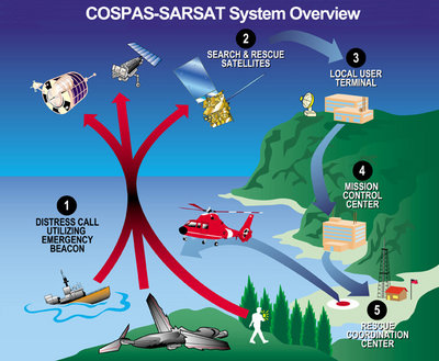

Overview diagram of EPIRB/COSPAS-SARSAT communication system
There are several systems in use, with beacons of varying expense, different types of satellites and varying performance.
23. GPS-BASED
The most modern 406 MHz beacons with GPS (US$ 1200-$3000 in 2002) locate a beacon with a precision of 100 meters, anywhere in the world, and send a serial number so the government authority can look-up phone numbers to notify next-of-kin in four minutes, with rescue commencing shortly afterward. The GPS system permits stationary, wide-view geosynchronous communications satellites to enhance the doppler position received by low Earth orbit satellites.
24. HIGH-PRECISION
An intermediate technology 406 MHz beacon (US$ 900-500) has world-wide coverage, locates within 2 km. (12.5 km² search area), notifies kin and rescuers in 2 hours maximum (46 min avg.), and has a serial number to look up phone numbers, etc. This can take up to two hours because it has to use moving weather satellites to locate the beacon. To help locate the beacon, the beacon's frequency is controlled to 2 parts per billion, and its power is a hefty five watts.
Both of the above types of beacons usually include an auxiliary 25 milliwatt beacon at 121.5 MHz to guide rescue aircraft.
25. TRADITIONAL ELT
The oldest, cheapest (US$ 139) beacons send an anonymous warble at 121.5 MHz. They can be detected by satellite over only 60% of the earth, require up to 6 hours for notification, locate within 20 km (search area of 1214 km²) and are anonymous. Coverage is partial because the satellite has to be in view of both the beacon and a ground station at the same time - the satellites do not store and forward the beacon's position. Coverage in polar and south-hemisphere areas is poor. The frequency is the standard aviation emergency frequency, and there is interference from other electronic and electrical systems, so false alarms are common. To reduce false alarms, a beacon is confirmed by a second satellite pass, which slows notification to 4 hours. Also, the beacons can't be located as well because their frequency is only accurate to 50 parts per million, and they send only 75-100 milliwatts of power.
By international agreement, these original 121.5 MHz (civil) and 243 MHz (military) beacons will no longer be sensed by satellites starting in 2009. However, pilots and ground stations are encouraged to continue to monitor for transmissions on the emergency frequencies.
Note that even the oldest systems provide an immense improvement in safety, compared to not having a beacon.
26. LOCATION BY DOPPLER (WITHOUT GPS)
When the beacon has no GPS receiver, the system locates the beacon from its doppler shift as received by the quickly-moving satellites. Basically, the frequency received varies depending on the speed of the beacon relative to the satellite. The amount of doppler is proportional to the range and bearing to the satellite. The instant the beacon's doppler shift changes from high to low indicates the time when the bearing from the beacon to the satellite's ground track is 90 degrees. The side of the satellite track is determined because the rate of change of the doppler is faster when the Earth is turning towards the satellite track.
In order to handle multiple simultaneous beacons, modern 406 MHz beacons transmit in bursts, and remain silent for a few seconds. This also conserves transmitter power.
The Russians developed the original system, and its success drove the desire to develop the improved 406 MHz system. The original system is a brilliant adaptation to the low quality beacons, originally designed to aid air searches. It uses just a simple, lightweight transponder on the satellite, with no digital recorders or other complexities. Ground stations listen to each satellite as long as it is above the horizon. Doppler shift is used to locate the beacon(s). Multiple beacons are separated when a computer program performs a Fourier transform on the signal. Also, two satellite passes per beacon are used. This eliminates false alarms by using two measurements to verify the beacon's location from two different bearings. This prevents false alarms from VHF channels that affect a single satellite. Regrettably, the second satellite pass almost doubles the average time before notification of the rescuing authority. However the notification time is much less than a day.
27. SATELLITES
Receivers are auxiliary systems mounted on several types of satellites. This substantially reduces the program's cost.
The weather satellites that carry the SARSAT receivers are in "ball of yarn" orbits, inclined at 99 degrees. The longest period that all satellites can be out of line-of-sight of a beacon is about two hours.
The first satellite constellation was launched in the early 1970s by the Soviet Union, Canada, France and the USA.
Some geosynchronous satellites have beacon receivers. Since end of 2003 there are four such geostationary satellites (GEOSAR) that cover more than 80% of the surface of the earth. As with all geosynchronous satellites, they are located above the equator. The GEOSAR satellites do not cover the polar caps.
Since they see the Earth as a whole, they see the beacon immediately, but have no motion, and thus no doppler frequency shift to locate it. However, if the beacon transmits GPS data, the geosynchronous satellites give nearly instantaneous response.
28. HISTORY
The original impetus to the program in the U.S. was the loss of Congressmen Hale Boggs and Nick Begich in the Alaskan wilderness on October 16, 1972. A massive search effort failed to locate them. The result was a U.S. law mandating that all aircraft carry an emergency locator transmitter. Technical and organizational improvements followed.
Cospas-Sarsat is an international organization that has been a model of international cooperation, even during the Cold War. SARSAT means Search And Rescue SATellite. COSPAS is a Russian acronym with the same meaning. A consortium of Russia, the U.S., Canada and France formed the organization in 1982. Since then 29 others have joined.
Cospas-Sarsat defines standards for beacons, auxiliary equipment to be mounted on conforming weather and communication satellites, ground stations, and communications methods. The satellites communicate the beacon data to their ground stations, which forward it to main control centers of each nation that can initiate a rescue effort.
The U.S. Coast Guard once promoted an emergency beacon on maritime VHF emergency channels. It now promotes the superior Cospas-Sarsat system, and no longer services.
REFERENCES
Astronautics summary and prospects / Kiselev, Medvedev, Menshikov, Wien: Springer, 2005
Astronomie und Astrophysik / A. Weigert, H.J. Wendker, Berlin: Springer, 2004
Astronomy / Moché: Wiley&Sons, 2004
Astronomy – The evolving Universe / Michael Zeilik: Wiley&Sons 1997
Astrowissen / Hans-Ulrich Keller: Stuttgart: Franck-Kosmos, 1994
Der NASA Atlas des Sonnensystems / Knaur: 2001
Der neue Kosmos / A. Unsöld, B. Baschek, Springer: 2002
Die Technik des modernen Verkehrsflugzeuges / Hünecke, Motorbuch Verlag: 1998
Elektrotechnik / Metz, Naundorf, Schlabbach, Hanser: 1998
Flugnavigation / Kühr: 1996
Flugnavigation / Mies: 1998
Flugtechnik / Mies: 1996
Funknavigation / Kühr: 1996
Grundlagen der Elektrotechnik / Hagmann, Aula: 2005
Grundlagen der Flugwetterkunde / Kühr: 1996
Handbuch der Luftfahrt / Mensen, Springer: 2003
Introduction to Airborne Radar / Stimson, SciTech Publishing, Inc.: 2004
Luftfahrt-Definitionen / Cescotti, Motorbuch: 1994
Luftfahrzeugtechnik / Götsch, Motorbuch: 2003
Luftrecht / Kühr: 1996
Satellitennavigation / Kupzog, Kühr: 2004
Technik I / Kühr: 1996
Technik II / Kühr: 1996
Technisches Wörterbuch / Lufthansa Flight Training, Bremen: 1998
The Pilot’s Manual, Private & Commercial / Trevor Thom, Aviation Supplies & Academics: 1998
The Standard Handbook for Aeronautical and Astronautical Engineers / Mark Davies, McGraw-Hill Professional Publishing: 2002